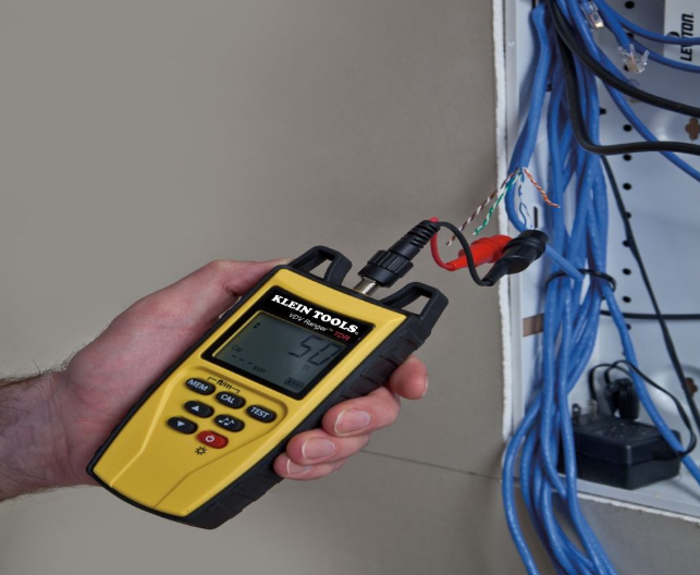
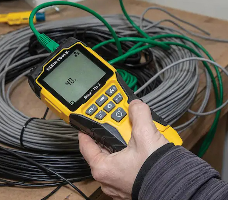
Time domain reflectometers are devices used to locate and characterise impedance changes in cable systems that result from faults, joints, open connections, deteriorated neutrals, taps in the cable system, bad connectors, water ingress and other types of anomalies that affect the impedance characteristics of the system.
A time domain reflectometer, also known as a TDR cable tester, operates like a radar. A fast-rise time pulse is sent into the cable system at one end, and as that pulse goes down the cable, changes in the impedance characteristics will cause the signal to be reflected back towards the unit. The reflected pulse parts can be positive on negative depending on whether the impedance is greater or lesser than the characteristic impedance of the cable.
The initial and reflected pulses are plotted against time on the unit, similar to an oscilloscope. The instrument can be tuned to determine the speed of the pulse in the cable system, in order to determine the conductor distance to the end of the system. You can use a TDR cable tester to find discontinuities represented by reflected pulses. Moreover, the shapes of reflected pulses can help you determine the nature of the discontinuity.
How is Testing Applied?

Testing is generally performed offline, a fast-rise time, low-voltage pulse is applied between the conductor and insulation shield of cable systems at an elbow or termination. As the pulse goes through the system, reflections are produced by changes in impedance and discontinuities.
The pulses are displayed against time on an oscilloscope display and are interpreted by the person performing the test. Since the velocity of propagation of the pulses is known or can be estimated, the time can be converted to location or distance. An experienced tester can determine the source of impedance discontinuity by the magnitude and shape of the reflected signal.
The test duration can be anywhere between 5 and 10 minutes once the device and the cable system are connected. The advantages of TDR measurements include:
- Easy testing
- Test equipment is portable and affordable
- Uses low-test voltage
- Provides historical data to increase the value of future tests by observing trends
- Locates areas of the system with impedance-related issues
However, there are also some potential issues and disadvantages to using TDRs, such as:
- Unclear whether online tests can be performed
- Interpretation of data may require a history of cable construction
- Test voltage of low-voltage time domain reflectometers may not be sufficient enough to locate dielectric imperfections
- It can be hard to interpret certain impedance discontinuities
- It can be hard to interpret results on circuits that feature multiple taps
- It can be hard to interpret results on tape-shielded cables
- Requires skilled testers to test and analyze results
- There are blind spots at the near end where the pulse is sent
- Electrical noise can interfere with low-voltage signals
- Successfully locating an impedance discontinuity will depend on having the right velocity of propagation, plus the underground cable layout
One of the most important things to remember when performing TDR measurements is that the length reading on the unit is related to the cable system conductor length and not the surface distance between the far and near ends of the system being tested. This creates two challenges – the first one relates to the relationship between how the cable system is arranged and how that impacts locating an anomaly, whereas the second one is the error on the velocity of propagation directly impacts the length readings, thus the interpretation results of the TDR.
Popular Testers

AEMC CA7024 TDR Cable Fault Locator & Length Meter
A hand-held, alphanumeric unit designed to measure the length of communication and electrical cables. It incorporates fast-edge step TDR tech, and is capable of measuring to a range of 2000m on at least two conductors. Some of its most notable features include automatic cable impedance compensation, manual selection of voltage of propagation for all cables not found in the library, a built-in library of common cables and their velocity of propagation, the velocity of propagation setting displayed along the length and cable type, CE mark, large high-visibility blue electroluminescent backlit display.
BI Communications TX4000 Graphical Time Domain Reflectometer TDR
Another hand-held unit with 11 range scales, covering 0 to 4000 metres. It also features a 7-metre first-range scale and a 0.5-metre dead zone. The near and far end faults are displayed on a backlit LCD of 128×64 pixels. It also comes with an Auto Fault Location feature that moves the cursor right onto the first fault or event, reducing the need to visually interpret waveforms. You can also set it in manual mode to make the waveform visually scannable as on other TDRs. It also comes with a scan lock feature that allows you to hold the trace for closer examination. You can easily identify and locate faults on metallic cables with multiple insulated conductors. Last but not least, it comes in a rugged IP54-rated, ABS housing and weighs only 350 grams.


